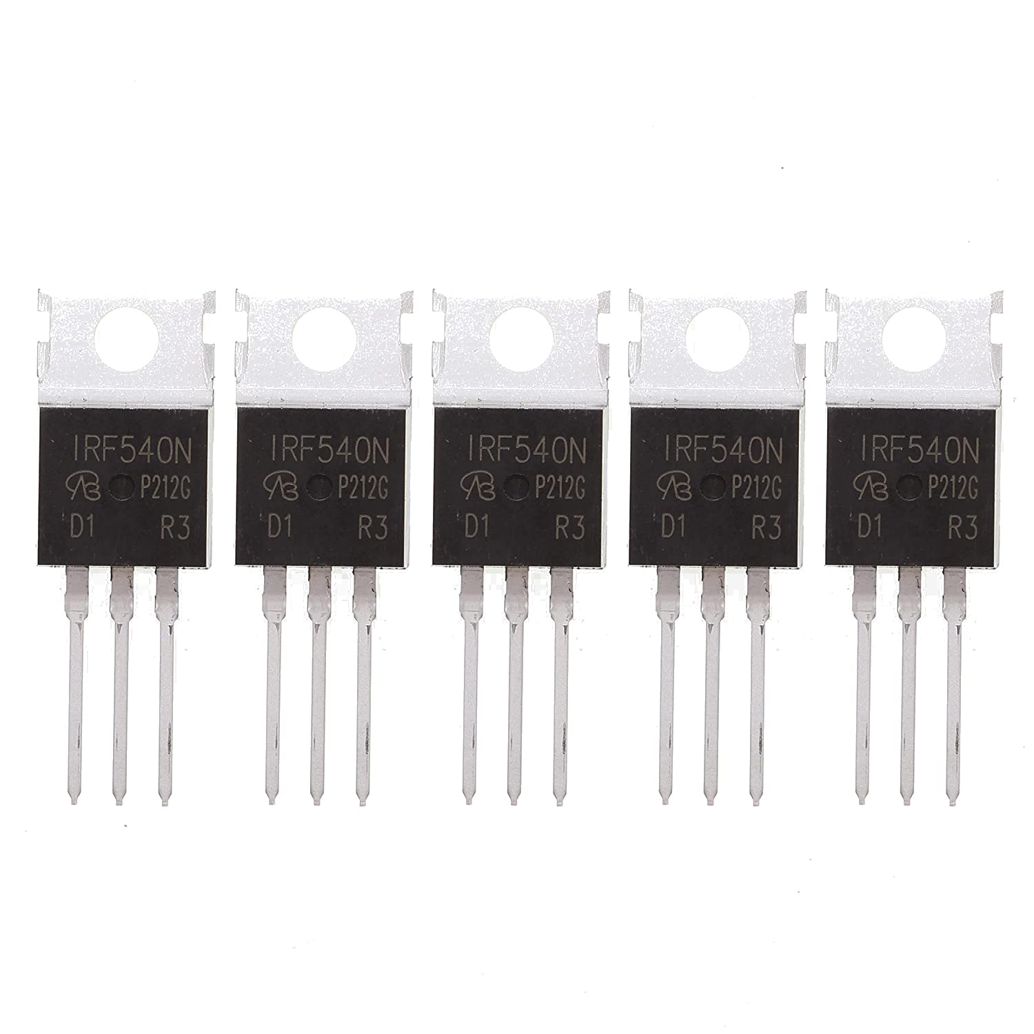
The IRF540N is a popular N-channel MOSFET widely used in various electronic applications due to its high efficiency, low on-resistance, and robust performance. This article delves into the IRF540N's specifications, uses, differences from the IRF540, operational principles, and how to properly connect it in a circuit.

IRF540N Datasheet
The IRF540N is a power MOSFET designed for switching and amplification in high-power applications. Here are some key specifications from the IRF540N datasheet:
- Drain-Source Voltage (V_DS): 100V
- Continuous Drain Current (I_D): 33A at 25°C
- Gate-Source Voltage (V_GS): ±20V
- R_DS(on) (On-Resistance): 44mΩ at V_GS = 10V
- Total Gate Charge (Q_g): 67nC
- Operating Temperature Range: -55°C to +175°C
- Package Type: TO-220
These specifications make the IRF540N suitable for high-current, low-voltage applications where efficiency and fast switching are crucial.
What is IRF540N Used For?
The IRF540N is used in various applications due to its versatility and high performance:
- Switching Power Supplies: Commonly used in DC-DC converters, power supplies, and inverters where efficient switching is essential.
- Motor Control: Ideal for driving motors, particularly in robotics and automation, where it can handle significant current loads.
- LED Drivers: Used in LED dimming and control circuits where precise current regulation is needed.
- Audio Amplifiers: Employed in Class D amplifiers for efficient power delivery.
- Solar Inverters: Utilized in solar power systems for converting DC to AC efficiently.
The IRF540N’s ability to handle high currents and voltages makes it a go-to component in both hobbyist and professional electronics.
What is the Difference Between IRF540 and IRF540N?
The IRF540 and IRF540N are very similar, but the "N" version offers some improvements:
- On-Resistance (R_DS(on)): The IRF540N has a lower on-resistance (44mΩ) compared to the IRF540, which typically has a slightly higher on-resistance. This means the IRF540N is more efficient with less heat dissipation during operation.
- Switching Speed: The IRF540N has improved switching characteristics, making it better suited for high-speed switching applications.
- Gate Charge: The IRF540N generally has a lower total gate charge, which reduces the power required to drive the MOSFET and improves overall efficiency.
While both MOSFETs are suitable for similar applications, the IRF540N is often preferred in more demanding environments due to its enhanced performance.
How Does IRF540 Work?
The IRF540N, like all MOSFETs, operates by controlling the flow of current between the drain and source terminals, with the gate terminal acting as the control input. Here's how it works:
- N-Channel Operation: The IRF540N is an N-channel MOSFET, meaning it conducts when a positive voltage is applied to the gate relative to the source. This creates a conductive channel between the drain and source.
- Gate Voltage Control: When the gate voltage (V_GS) exceeds the threshold voltage (typically around 2-4V for the IRF540N), the MOSFET turns on, allowing current to flow from the drain to the source.
- Switching: In switching applications, the MOSFET is rapidly turned on and off, controlling the current flow through the load. The efficiency of this process is largely determined by the on-resistance and gate charge of the MOSFET.
The IRF540N’s ability to handle high currents with minimal losses makes it ideal for switching applications in power electronics.
How to Connect IRF540N?
Connecting the IRF540N in a circuit involves correctly wiring its three terminals: the gate, drain, and source.
-
Gate (G): Connect the gate to the control signal, usually from a microcontroller or other logic circuit. A gate resistor (typically 10-100Ω) can be used to limit the current and prevent damage to the MOSFET.
-
Drain (D): Connect the drain to the load. For example, if driving an LED, the drain would be connected to the negative side of the LED, with the positive side connected to the power supply.
-
Source (S): Connect the source to ground (0V) in an N-channel MOSFET configuration. This allows the current to flow from the drain through the MOSFET when the gate is activated.
In some cases, a pull-down resistor (10kΩ) is used between the gate and source to ensure the MOSFET remains off when the gate signal is not present. For switching high-power loads, a heat sink may also be necessary to dissipate heat generated during operation.
Conclusion
The IRF540N is a versatile and powerful N-channel MOSFET suitable for a wide range of applications, from motor control to power supply switching. Understanding its datasheet, operational principles, and the differences between similar MOSFETs like the IRF540 allows for optimized use in various circuits. Properly connecting the IRF540N ensures reliable performance and longevity in your electronic projects.
Facts Checked by Hugh Johnson
Hugh Johnson stands tall in the realms of both the Integrated Circuits (ic Chips) industry and the electronic parts industry, earning acclaim as an esteemed expert in these fields. With an extensive background steeped in semiconductor technology, Hugh's expertise transcends chip design and fabrication, encompassing a profound understanding of electronic components' intricate functionalities and applications. His seasoned knowledge spans diverse facets, from microchip architecture and fabrication techniques to the broader landscape of electronic parts utilized across industries.


