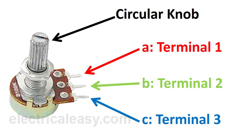
Potentiometers, commonly known as pots, are versatile components used in electronic circuits to control variables such as volume, brightness, and speed. Proper wiring of potentiometers is crucial for their functionality and optimal performance. In this article, we'll explore the essential aspects of potentiometer wiring, including connection methods, color coding, polarity, and identifying terminal configurations.
How should a potentiometer be wired?
Potentiometers typically have three terminals: the input terminal (usually called "1"), the output terminal ("3"), and the wiper terminal ("2"). To wire a potentiometer, the input and output terminals are connected to the circuit, while the wiper terminal is connected to the input or output, depending on whether it's used as a voltage divider or variable resistor. Helpful resource: https://www.instructables.com/Wire-a-Potentiometer-as-a-Variable-Resistor/

image source: https://mallgoodsm.life/product_details/7145952.html
What is the color code for potentiometer wiring?
Potentiometers may come with color-coded terminals to indicate their functionality. While color codes can vary between manufacturers, a common convention for potentiometer terminals is:
- Terminal 1: Usually black or another dark color
- Terminal 2 (wiper): Often white or another light color
- Terminal 3: May be red or another bright color
However, it's essential to consult the datasheet or documentation provided by the manufacturer for precise information regarding terminal identification. Helpful resource: https://support.biamp.com/Audia-Nexia/Control/Logic_Box-VCB/Wiring_potentiometers_to_the_Voltage_Control_Box
Which side of the potentiometer is positive?
Potentiometers are passive components and do not have a specific positive or negative side. However, when used in voltage divider circuits, the input terminal (Terminal 1) is typically connected to the positive voltage source, while the output terminal (Terminal 3) is connected to ground or the load. Helpful resource: https://www.youtube.com/watch?v=7xiHtAwyFgc
What are the three poles on a potentiometer?
The three poles on a potentiometer correspond to its three terminals: Helpful resource: https://www.wikihow.com/Wire-a-Potentiometer
- Terminal 1: The input terminal, often connected to the positive voltage source in voltage divider applications.
- Terminal 2 (Wiper): The moving terminal that makes contact with the resistive element, allowing adjustment of the output voltage or resistance.
- Terminal 3: The output terminal, usually connected to ground or the load in voltage divider circuits.
Understanding the function of each terminal is essential for proper potentiometer wiring and circuit operation.
In conclusion, wiring a potentiometer correctly is crucial for its effective use in electronic circuits. By following standard wiring practices, understanding color codes, and identifying terminal configurations, electronics enthusiasts and professionals can ensure reliable and efficient operation of potentiometers in their projects. Whether used for volume control in audio systems or dimming lights in lighting circuits, potentiometers provide versatile control options when wired correctly.
Facts Checked by Hugh Johnson
Hugh Johnson stands tall in the realms of both the chip industry and the electronic parts industry, earning acclaim as an esteemed expert in these fields. With an extensive background steeped in semiconductor technology, Hugh's expertise transcends chip design and fabrication, encompassing a profound understanding of electronic components' intricate functionalities and applications. His seasoned knowledge spans diverse facets, from microchip architecture and fabrication techniques to the broader landscape of electronic parts utilized across industries.


